| After the establishment of the valve
as a reliable amplifying device, improvement in circuitry was
a continuous research task for engineers. Over the years, many
amplifier circuits appeared in technical literature. The most
significant circuits used for high-quality sound system are
listed chronologically as follws:
|
|
1913 - Push-Pull circuit:
Conceived by E. H. Colpitts, this basically a balanced
circuit. The two valves can operate in several modes,
class A, AB or B supplying great output power while
canceling much of distorsion.
|
 |
| Simplified output circuit of a
conventional push-pull amplifier |
|
|
| 1927 - Negative-feedback
circuit. This circuit was developed by H. S. Black. Please
see the section "Classic Circuits". |
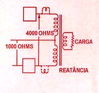
1947 - Circuito ultra linear:
D.T.N. Williamson, in England, projected this circuit
for ultra-linear operation.
|
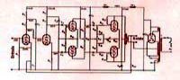 |
| The Williamson circuit used in
high-quality amplifiers. |
|
1949
- Symmetric Push-Pull circuit:
In 1949, F. C. McIntosh patented an efficient amplification
circuit. This simmetric push-pull circuit consists essenssially
of beam-power valves operating with a bifilar-wound output
transformer, with the beam-forming plates in the tube
cross-connected. |
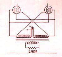 |
| The McIntosh
circuit |
|
|
1950 - Hafler-Keroes circuit:
David Hafler and Herbet I. Keroes developed an ultralinear
amplifier configuration generally known as the Hafler-Keroes
circuit. It is conceived in such away tht the screen
grid of the valve is returned to the output transformer
at a point representing about 18,5% of the impedance
of the primary winding. This circuit represents an intermediate
mode of operation, giving the power output of a pentode
and the low output impedance of a triode.
|
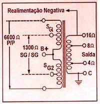 |
| Transformer
connections in the Hafler-Keroes circuit. |
|
|
|
|