 |
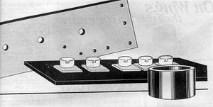
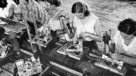
| Fig. 302 - The breedboard assembling. |
The first factory made receivers was built using the breedboard
approach. Therefore, soon due to the evolution of electrical
components as the resistors, capacitors, transformers, loudspeakers
and the thermionic valve, the breedboard
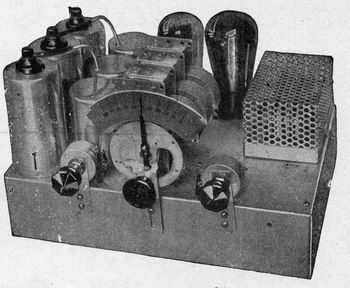 |
| Fig. 303 - A typical electro-mechanical
assembling showing the allocation of the tunining scale
or dial. |
technique was replaced by the metal chassis that improved so
much the receiver’s components electro-mechanical assembling.
Originally the metal chassis was made employing several mechanical
processes, such as: stamping, punching, bending and soldering;
finally, for aesthetic and protection purposes, it was coated
with an electroplated zinc layer. Fig 302
Essentially the chassis design should be mechanically and
electrically practical in such away to improve the receiver
operation. In this way,
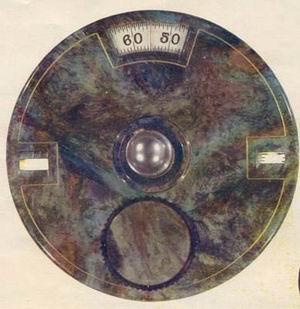 |
| Fig. 303A - An early type of dial or
tuning scale. |
the tunning scale or dial should be allocated for an easy reading.
Due to circuit innovation the tunning scale was provided with
the first mechanically operated tunning indicators, later replaced
by the
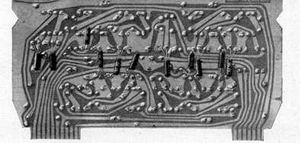 |
| Fig. 304 - The transistor era brought
a new technique in the electro-mechanical assembling –
the printed circuit board. |
well-known magic eye, requiring more functional and rationalized
design. Fig. 303
Yet, the receiver’s control ergonomy was deeply related
with the cabintet design for an easy operation through the
use of proper knobs.
In the early 1950’ transistor started a revolution in
the electro-mechanical assembling due to the miniaturization
of components as well as the introduction of the printed circuit
technique. Fig. 304
Therefore the aforeseen innovations gave birth to a new family
of materials, since then a perenial research task in the electronic
industry. Fig 305
 |
| Fig. 305 - The on line radio receiver
electro-mechanical assembling. |
|
|