|
|
|
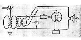
Schematic of the regenerative circuit
invented by Armstrong
|
|
Early types of radio receivers, either crystal as well as one-valve sets were unable to detect long distance radio signals. In this way soon appeared in the market the first multiples stages receivers by using several types of circuits’ topology.
One of such innovative receivers appeared in 1912. As known as regenerative circuit it was invented by Edwin H. Armstrong. After a long basis study of the De Forest’s original three element valve or AUDION, Armstrong concluded it behaves like an amplifier as well as an electromagnetic waves generator. In the regeneration circuit topology the valve as an amplifying device has its output connected to its input through a feedback loop providing a positive feedback and in this way strengthen the signal intensity deeply.
Soon, in 1916, Ernst Alexanderson patented the circuit topology as known as tuned radio frequency. Basically it consists of one or more tuned radio frequency amplifying stages followed by a detector or demodulator circuit in order to strengthen the signal intensity, generally followed by an audio frequency amplifier feeding sound to an ear phone or loudspeaker.
By using multiple R.F. amplifying stages, this type of circuit improved the radio selectivity deeply. Therefore, it requires that all the radio’s tuned R.F. stages must track and tune simultaneously the desired reception frequency. Firstly the R.F. stages employed three elements valves or triodes and later on tetrodes and pentodes counterparts.
Therefore, one major problem of TRF receivers built with triodes was the valve’s interelectrode capacitance which feeds energy in the output circuit to feedback into the input. The feedback could cause instability or oscillation during the signal’s reception and arisen undesired squealing or howling noises in the ear phone or loudspeaker.
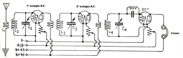 |
Schematic of tuned radio frequency employng two R.F. amplification stages |
In order to overcome such TRF’s circuit handicap, in 1922, Louis Alan Hazeltine and Harold Wheeler working at Steven Institute of Technology, USA developed a neutralization technique later on Christened as neutrodyne. The neutrodyne circuit consists of a TRF circuit topology modification in such way the triode valve’s interelectrode capacitance could be neutralized and suppressing the parasitic oscillations.
Thus, in a tuned radio frequency receiver every R.F. amplification stage was provided with an additional circuit which fed back a small amount of energy from the output to the input circuits bearing an opposite phase to suppress or neutralize the feedback through the tube's interelectrode capacitance, responsible for the parasitic oscillations, and so effectively preventing the undesired high-pitched squeals in the ear phone or loudspeaker.
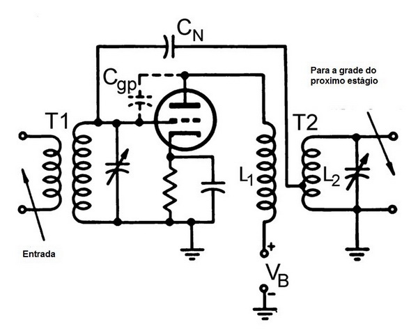 |
The condensed schematic of the neutrodyne circuit. The capacitor CN applies a second feedback signal to the valve’s grid. It is 180° degrees out of phase with the original signal and so by neutralizing it, which consequently suppress the oscillations. The signal is taken from an opposite phase winding (b) on the inter-stage coupling transformer T2. |
In spite of the Hazeltine’s innovation, the tuned radio frequency receiver still faced problems as when tuning in a radio station each R.F. amplifying stage had to be individually adjusted to the station's frequency arisen a tedious situation for the listener.
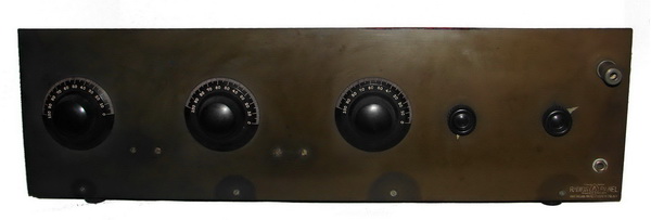 |
A typical vintage tuned radio frequency receiver’s Bakelite front panel showing the three R.F. amplifying stage knobs duly set at the same broadcasting radio station frequency position. The broadcasting station tuning was set by adjusting individual and simultaneously the three stages to match the respective frequency arisen a boring and tedious operation for the radio listener. |
However, during early thirties with the growth of the broadcasting radio stations soon operating in frequencies higher than 10 MHz, those types of receivers had difficulties to detect them.
In 1919, Armstrong again invented a new radio receiver technique design as known as super-heterodyne circuit. Such kind of circuit was more selective and stable and so became the radio receiver manufacturing backbone.
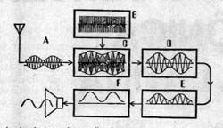 |
Schematic of the super heterodyne circuit invented by Armstrong circa 1919, where:
a - signal
b - oscillator
c - mixer
d - IF amplifier
e - detector
f - audio amplifier |
The radio boom started in early thirties pressing the science and technology even more for new radio receiver innovations. In 1933 it was launched in the market a new broadcasting radio system aimed to operate in high frequency range as known as frequency modulation or FM. Invented by the not so famous Major Armstrong in this new system concept it was possible to eliminate the phenomenon of static which plagued radio transmissions by using the amplitude modulation or AM.
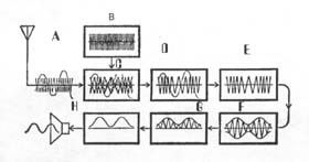 |
Schematic of the FM circuit invented by Armstrong in 1933 where:
a- signal
b- oscillator
c- mixer
d - IF amplifier
e - limiter
|
|